Easitrac - Turnout Operating Unit
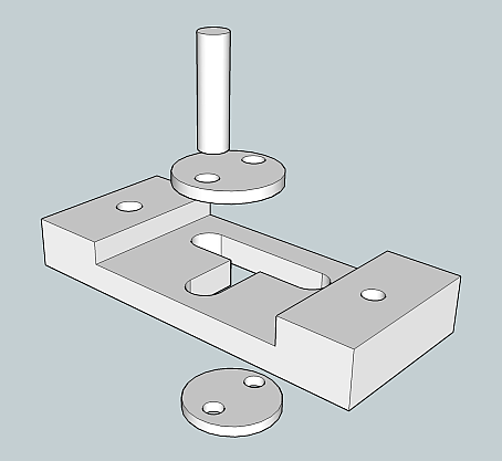 Solder small pin to the small discs, trapping the tie bar part between them,
but with enough slack to allow tie bar to rotate/slide between the discs.
Solder small pin to the small discs, trapping the tie bar part between them,
but with enough slack to allow tie bar to rotate/slide between the discs.
 Solder the inner spindle to the discs. This creates a cam from the discs
and pins.
Solder the inner spindle to the discs. This creates a cam from the discs
and pins.
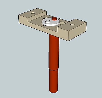
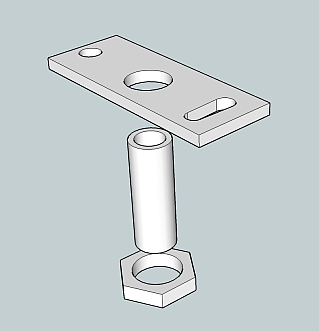 Assemble the below baseboard fixing plate, threaded tube and large locknut.
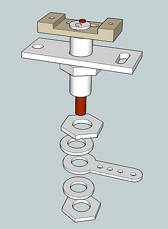 Slide tiebar/cam assembly into baseboard fixing tube, secure operating lever
with smaller nuts and washers as shown.
Slide tiebar/cam assembly into baseboard fixing tube, secure operating lever
with smaller nuts and washers as shown.
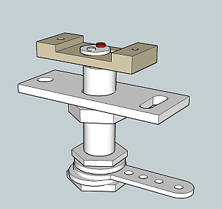 Assembled unit should look like this (probably neater as your washers will
be the right size!). Operating lower lever will cause the upper tie bar
to slide side to side (left to right in drawing).
Assembled unit should look like this (probably neater as your washers will
be the right size!). Operating lower lever will cause the upper tie bar
to slide side to side (left to right in drawing).
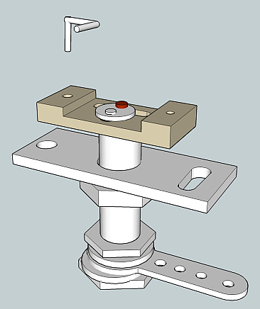 Bend up the blade fixing wires as shown, jig shown lower down the page (two
required, only one shown, they are handed).
Bend up the blade fixing wires as shown, jig shown lower down the page (two
required, only one shown, they are handed).
 Fix blade (right rail in sketch) to operating wire, stock rail (left in
sketch) rests on horizontal of operating wire, thus ensuring blade remains
at correct height.
Fix blade (right rail in sketch) to operating wire, stock rail (left in
sketch) rests on horizontal of operating wire, thus ensuring blade remains
at correct height.
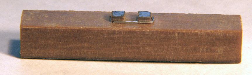
A piece of 0.3mm wire is inserted into the jig, and bent around the raised
parts as shown. Tweaking in pliers to get 90 degree bends may be necessary.
Note the jig has two holes drilled, and can make LH and RH versions of the
wire.
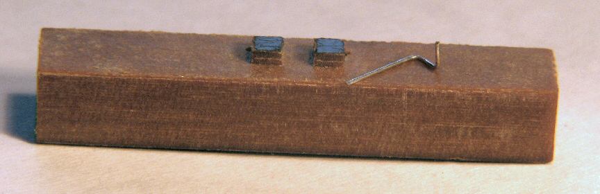
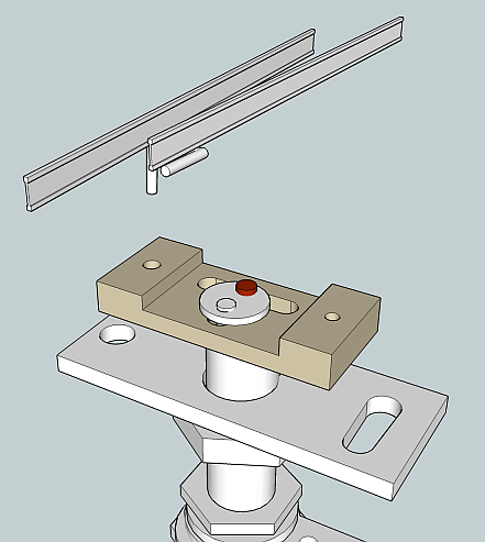
Finished bent wire resting on top of jig. Solder one end alongside the blade
and fit the other end into the turnout operating unit.
